Sensing#
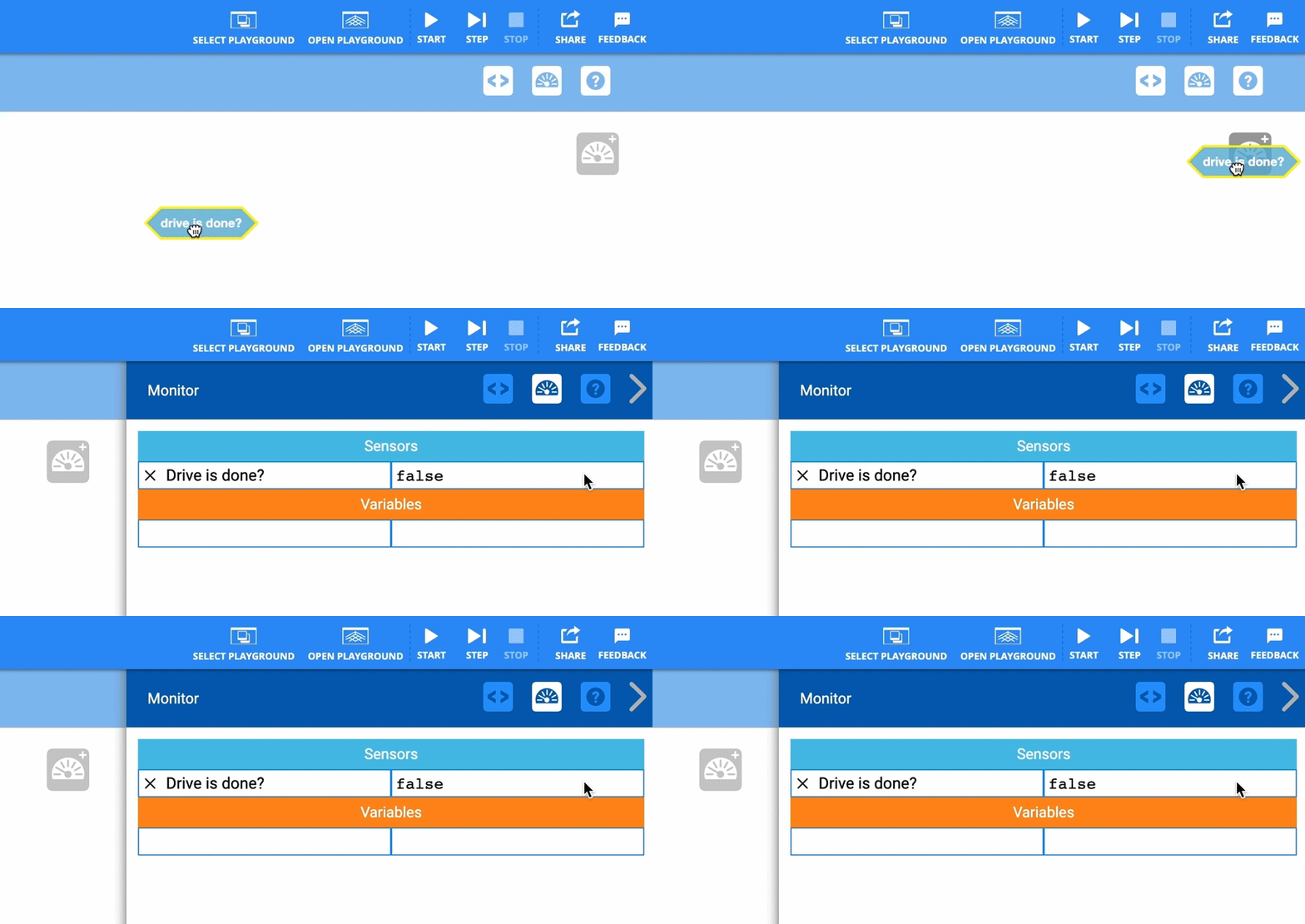
To put a sensor in the Monitor Console, drag and drop its block to the Monitor Icon on the right side of the screen.
Timer#
Reset timer#
The Reset timer block is used to reset the Brain’s timer.
reset timer
The Brain’s timer begins at the beginning of each project. The reset timer block is used to reset the timer back to 0 seconds.
In this example, the VR Robot will drive forward for 3 seconds before the Brain’s timer is reset and the Drivetrain stops.
  when started
  drive [forward v]
  wait (3) seconds
  reset timer
  stop driving
Timer value#
The Timer value block is used to report the value of the Brain’s timer in seconds.
(timer in seconds)
The Brain’s timer starts at 0 seconds when the program starts and reports the timer’s value as a decimal value.
The Timer value reporter block is used inside of blocks with circular spaces.
In this example, the VR Robot will wait for 3 seconds before printing the current timer value in the Print Console.
  when started
  wait (3) seconds
  print (timer in seconds) ▶
Drivetrain#
Drive is done#
The Drive is done block is used to report if the Drivetrain has completed its movement.
<drive is done?>
The Drive is done block reports True when the Drivetrain’s motors have completed their movement.
The Drive is done block reports False when the Drivetrain’s motors are still moving.
The Drive is done block is used in blocks with hexagonal (six-sided) spaces.
In this example, the Drivetrain will drive forward for 50 inches. One second after the VR Robot has started moving, the code will begin to check if the Drivetrain has stopped. Once it is done moving, it will print its message to the Print Console.
  when started
  drive [forward v] for (50) [inches v] ◀ and don't wait
  wait (1) seconds
  wait until <drive is done?>
  print [The Drivetrain has finished moving. ] ▶
Drive is moving#
The Drive is moving block is used to report if the Drivetrain is currently moving.
<drive is moving?>
The Drive is moving block reports True when the Drivetrain’s motors are moving.
The Drive is moving block reports False when the Drivetrain’s motors are stopped.
The Drive is moving block is used in blocks with hexagonal (six-sided) spaces.
In this example, the VR Robot will move forward for 50 inches. After 1 second, if the Drivetrain is still in motion, it will print a message to the Print Console.
  when started
  drive [forward v] for (50) [inches v] ◀ and don't wait
  wait (1) seconds
  if <drive is moving?> then
  print [The Drivetrain is moving.] ▶
  end
Drive heading#
The Drive heading block is used to report the heading that the Drivetrain is facing by using the Gyroscopic (Gyro) sensor’s current angular position.
(drive heading in degrees)
The Drive heading reporter block reports a range from 0.00 to 359.99 degrees.
The Drive heading reporter block is used inside of blocks with circular spaces.
In this example, the VR Robot’s current drive heading will be printed to the Print Console.
  when started
  print (drive heading in degrees) ▶
Drive rotation#
The Drive rotation block is used to report the Drivetrain’s angle of rotation.
(drive rotation in degrees)
The Drive rotation reporter block reports a positive value when the Drivetrain turns in a clockwise direction.
The Drive rotation reporter block reports a negative value when the Drivetrain turns in a counter-clockwise direction.
The Drive rotation reporter block is used inside of blocks with circular spaces.
In this example, the VR Robot’s current angle of rotation will be printed to the Print Console.
  when started
  print (drive rotation in degrees) ▶
Bumper Sensor#
To identify which Bumper Sensors your VR Robot can utilize, please consult your Playground’s detail page.
Pressed bumper#
The Pressed bumper block is used to report if the Bumper Switch is pressed.
<[LeftBumper v] pressed?>
The Pressed bumper block reports True if the Bumper Switch is being pressed.
The Pressed bumper block reports False if the Bumper Switch is not pressed.
Choose which Bumper Switch to use.
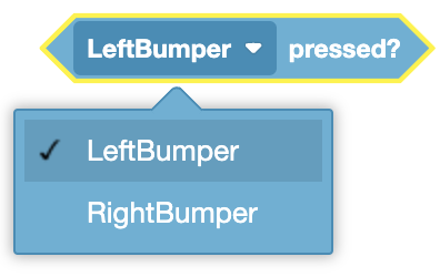
The Pressing bumper Boolean block is used in blocks with hexagonal (six-sided) spaces.
In this example, the VR Robot will drive forward as it continuously checks if its Right Bumper Sensor has been pressed. If the sensor is pressed, the Drivetrain will stop.
  when started
  drive [forward v]
  forever
  if <[RightBumper v] pressed?> then
  stop driving
  end
Distance Sensor#
To identify which Distance Sensors your VR Robot can utilize, please consult your Playground’s detail page.
Distance found object#
The distance found object block is used to report whether the built-in Distance sensor has found an object in front of the robot.
<[FrontDistance v] found an object?>
Choose which Distance Sensor to use.
The base VR Robot only has access to the Front Distance sensor.

The VR+ Robot has access to the Front, Left, and Right Distance sensors.
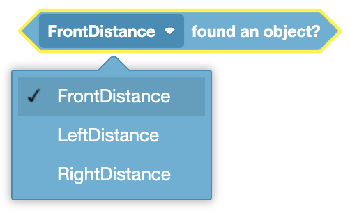
The Distance found object block reports True when the built-in Distance sensor sees an object or surface within its field of view, and within 3000 mm of the sensor.
The Distance found object block reports False when the built-in Distance sensor does not detect an object or surface within 3000 mm.
The Distance found object block is used in blocks with hexagonal (six-sided) spaces.
In this example, the VR Robot will turn right indefinitely until the Front Eye Sensor detects an object. When it detects an object, it will stop turning and print the distance between the sensor and the object in millimeters.
  when started
  turn [right v]
  wait until <[FrontDistance v] found an object?>
  stop driving
  print ([FrontDistance v] in [mm v]) ▶
Distance from#
The distance from block is used to report the distance of the nearest object.
([FrontDistance v] in [mm v])
Choose which Distance Sensor to use.
The base VR Robot only has access to the Front Distance sensor.
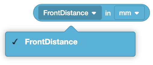
The VR+ Robot has access to the Front, Left, and Right Distance sensors.
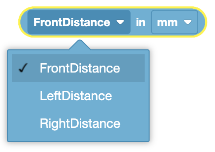
Choose whether the Distance from block reports in millimeters or inches.
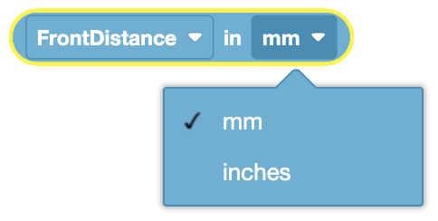
The Distance from block is used inside blocks with circular spaces.
In this example, the VR Robot will turn right indefinitely until the Front Eye Sensor detects an object. When it detects an object, it will stop turning and print the distance between the sensor and the object in millimeters.
  when started
  turn [right v]
  wait until <[FrontDistance v] found an object?>
  stop driving
  print ([FrontDistance v] in [mm v]) ▶
Eye Sensor#
To identify which Eye Sensors your VR Robot can utilize, please consult your Playground’s detail page.
Eye Sensor near object#
The Eye Sensor near object block is used to report if the Color Sensor Eye is close enough to an object to detect a color.
<[FrontEye v] is near object?>
Choose which Eye Sensor to use.
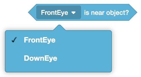
The Eye Sensor near object block reports True when the Color Sensor is close to an object that has detectable colors.
The Eye Sensor near object block reports False when the Color Sensor isn’t close enough to an object with detectable colors.
The Eye Sensor near object block is used in blocks with hexagonal (six-sided) spaces.
In this example, the VR Robot will drive forward until the Front Eye Sensor is close enough to the object to detect a color, then the Drivetrain will stop.
  when started
  drive [forward v]
  wait until <[FrontEye v] is near object?>
  stop driving
Eye Sensor detects color#
The Eye Sensor detects color block is used to report if one of the Color Sensor Eyes detects a specified color.
<[FrontEye v] detects [red v]?>
Choose which Eye Sensor to use.
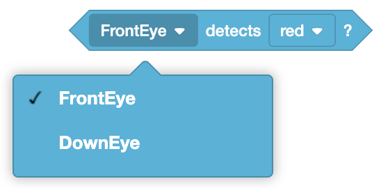
Choose which color to detect.
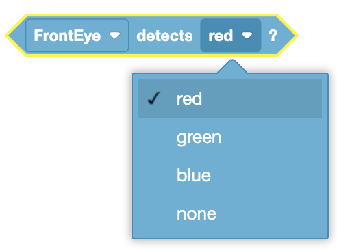
The Eye Sensor detects color block reports True when the Color Sensor Eye detects the selected color.
The Eye Sensor detects color block reports False when the Color Sensor Eye detects a different color than the one selected.
The Eye Sensor detects color block is used in blocks with hexagonal (six-sided) spaces.
In this example, the VR Robot will drive forward until the Front Eye Sensor detects a green object. When the Front Eye Sensor detects a green object, the VR Robot will turn right for 90 degrees.
  when started
  drive [forward v]
  wait until <[FrontEye v] detects [green v]?>
  turn [right v] for (90) degrees ▶
Color brightness#
The Color brightness block is used to report the brightness of an object from one of the Color Sensor Eyes.
([FrontEye v] brightness in %)
The Color brightness block reports the brightness of an object. White objects will report a brightness of 100%, black objects will report a brightness of 0%. All other colors will report a brightness between those values.
Choose which Eye Sensor to use.
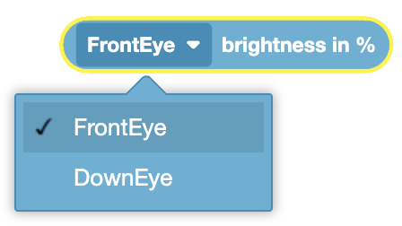
The Color brightness block is used in blocks with circular spaces.
In this example, the VR Robot will drive forward until the Front Eye Sensor is close enough to detect the color of the object, then it will stop and print the object’s current brightness.
  when started
  drive [forward v]
  wait until <[FrontEye v] is near object?>
  stop driving
  print ([FrontEye v] brightness in %) ▶
Location Sensor#
Position#
The Position block is used to report the X or Y coordinate position of the VR Robot.
(position [X v] in [mm v])
Choose whether to return the X coordinate or Y coordinate.
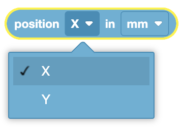
Choose whether the value is reported in mm or inches.
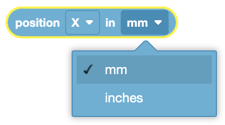
The Position block is used in blocks with circular spaces.
In this example, the VR Robot’s current Y position in millimeters will be printed to the Print Console.
  when started
  print (position [Y v] in [mm v]) ▶
Position angle#
The Position angle block is used to report the angle of the VR Robot in degrees.
(position angle in degrees)
The Position angle block is used in blocks with circular spaces.
In this example, the VR Robot’s current angle in degrees will be printed to the Print Console.
  when started
  print (position angle in degrees) ▶
