Arm#
Move 6-Axis Arm to Position#
The Move 6-Axis Arm to Position block is used to move the 6-Axis Arm to a specified set of coordinates.
This is can be a non-waiting or waiting block depending on if the and don’t wait option is used.
move [arm v] to position x:(120) y:(120 ) z:(75) [mm v] ▶
Select which 6-Axis Arm to move.

Select which unit for the coordinates to use: millimeters or inches.

You can select the arrow to expand and don’t wait - this will allow subsequent blocks to run while the 6-Axis Arm moves.
move [arm v] to position x:(120) y:(120 ) z:(75) [mm v] ◀ and don't wait
In this example, the 6-Axis Arm will move to the coordinates (120, 120, 75) in millimeters.
  when started
  move [arm v] to position x:(120) y:(120 ) z:(75) [mm v] ▶
Increment Move 6-Axis Arm Position#
The Move 6-Axis Arm to Position block is used to move the 6-Axis Arm in incremental distances using the specified values.
This is can be a non-waiting or waiting block depending on if the and don’t wait option is used.
increment [arm v] position by x:(0) y:(0) z:(0) [mm v] ▶
Select which 6-Axis Arm to move.

Select which unit for the coordinates to use: millimeters or inches.

You can select the arrow to expand and don’t wait - this will allow subsequent blocks to run while the 6-Axis Arm moves.
increment [arm v] position by x:(0) y:(0) z:(0) [mm v] ◀ and don't wait
In this example, the 6-Axis Arm will move for 100 millimeters along the X axis.
increment [Arm1 v] position by x:(100) y:(0) z:(0) [mm v] ▶
Move 6-Axis Arm to Orientation#
The Move 6-Axis Arm to Orientation block is used to rotate the 6-Axis Arm’s end effector about an axis to a specific orientation.
This is can be a non-waiting or waiting block depending on if the and don’t wait option is used.
move [arm v] to orientation [pitch v] (0) degrees ▶
Select which 6-Axis Arm to move.

Select which orientation to be moved.
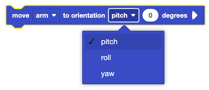
You can select the arrow to expand and don’t wait - this will allow subsequent blocks to run while the 6-Axis Arm moves.
move [arm v] to orientation [pitch v] (0) degrees ◀ and don't wait
In this example, the 6-Axis Arm will move its end effector to point at 270 degrees along the Z axis.
  when started
  move [arm v] to orientation [yaw v] (270) degrees ▶
Increment Move 6-Axis Arm Orientation#
The Increment Move 6-Axis Arm Orientation block is used to rotate the 6-Axis Arm’s end effector about an axis for an incremental distance in degrees.
This is can be a non-waiting or waiting block depending on if the and don’t wait option is used.
increment [arm v] orientation by [pitch v] (0) degrees ▶
Select which 6-Axis Arm to move.

Select which orientation to be moved.
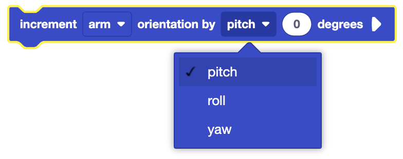
You can select the arrow to expand and don’t wait - this will allow subsequent blocks to run while the 6-Axis Arm moves.
increment [arm v] orientation by [pitch v] (0) degrees ◀ and don't wait
In this example, the 6-Axis Arm will move its end effector for 40 degrees along the Y axis.
  when started
  increment [arm v] orientation by [pitch v] (40) degrees  ▶
Set 6-Axis Arm Speed#
The Set 6-Axis Arm Speed block is used to set the 6-Axis Arm’s speed.
By default, the arm’s speed is set to 50% at the start of a project. The 6-Axis Arm’s speed can be set to an integer from 1-100%.
This is a non-waiting command and allows any subsequent commands to execute without delay.
set [arm v] speed to (50)% :: custom-arm
Select which 6-Axis Arm to move.
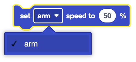
In this example, the 6-Axis Arm will set its speed to 30% before moving to (120, 120, 70).
  when started
  set [arm v] speed to (30)% :: custom-arm
  move [arm v] to position x:(120) y:(120) z:(70) [mm v] ▶
Set 6-Axis Robotic Arm End Effector#
The Set 6-Axis Robotic Arm End Effector block is used to set the 6-Axis Arm’s end effector.
This will automatically adjust the Z-offset of the 6-Axis Arm for what end effector is selected. By default, the end effector is set to the Magnet Pickup Tool at the start of the project.
This is a non-waiting command and allows any subsequent commands to execute without delay.
set [arm v] end effector to [magnet v]
Select which 6-Axis Arm’s end effector to set.
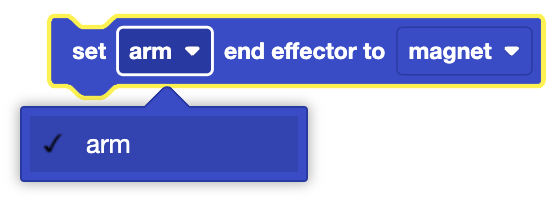
Select which end effector to set on the 6-Axis Arm.
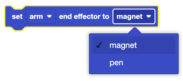
In this example, the 6-Axis Arm will set its end effector to the Pen Holder Tool.
  when started
  set [arm v] end effector to [pen v]
Set 6-Axis Arm Magnet Mode#
The Set 6-Axis Arm Magnet Mode block is used to set the 6-Axis Arm’s magnet mode indefinitely or until another Set 6-Axis Arm Magnet Mode Block is used.
At the start of a project, the Magnet Pickup Tool’s mode is reset to its default mode, released.
This is a non-waiting command and allows any subsequent commands to execute without delay.
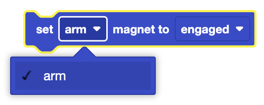
set [arm v] magnet to [engaged v]
Select which 6-Axis Arm to use.
Select which mode to set the Magnet Pickup Tool to:
Engaged - The Magnet Pickup Tool will pick up objects.
Released - The Magnet Pickup Tool will drop any object it is holding and not pick up further objects.
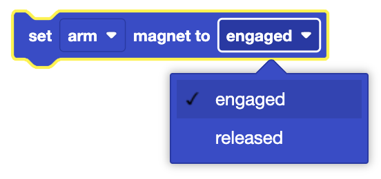
In this example, the 6-Axis Arm will set the Magnet Pickup Tool’s mode to engaged.
  when started
  set [arm v] magnet to [engaged v]
Set 6-Axis Robotic Arm Pen Offset#
The Set 6-Axis Robotic Arm Pen Offset block is used to manually set the 6-Axis Robotic Arm’s current Z offset.
You must use the Set 6-Axis Robotic Arm End Effector block to set the end effector to the Pen Tool before using this command, otherwise the Set 6-Axis Robotic Arm Pen Offset will do nothing.
The pen offset is the distance between the top of the Pen Holder Tool and the tip of the Dry-Erase Marker. At the start of a project, the Pen Offset is set to 0. By default, this corresponds to the ~23mm between the tip of the Dry-Erase Marker that is provided in the CTE Workcell Kit and the Pen Holder Tool.
The default offset of 0 will place the Z axis origin for the Arm at where the Pen Tool connects to the 6-Axis Arm.
This is a non-waiting command and allows any subsequent commands to execute without delay.
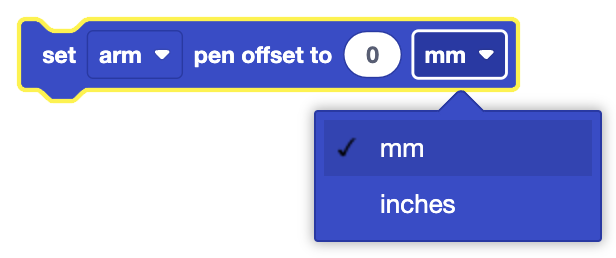
set [arm v] pen offset to (0) [mm v]
Select which 6-Axis Arm to use.
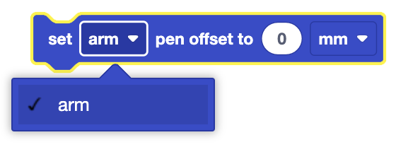
Select which unit to set the pen offset with: millimeters or inches.
In this example, the 6-Axis Arm’s pen offset is set to 1 inch before the 6-Axis Arm moves to the position (120, 120, 0).
  when started
  set [arm v] pen offset to (1) [inches v]
  move [arm v] to position x:(120) y:(120) z:(0) [mm v] ▶
Enable 6-Axis Arm Control Stop#
The Enable 6-Axis Arm Control Stop block is used to enable the 6-Axis Arm’s control stop.
A control stop will stop the 6-Axis Arm from continuing any further movement. Once this block is used, you will not be able to re-enable the 6-Axis Arm until you restart the project.
This is a waiting command and prevents any subsequent commands from executing.
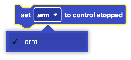
set [arm v] to control stopped
Select which 6-Axis Arm’s control stop to enable.
In this example, the 6-Axis Arm will move to (120, 120, 70) and then enable its control stop.
  when started
  move [arm v] to position x:(120) y:(120) z:(70) [mm v] ▶
  set [arm v] to control stopped
