Sensing#
Brain Sensing#
Reset Timer#
The Reset Timer block is used to reset the IQ Brain’s timer.
reset timer
The Brain’s timer begins at the beginning of each project. The reset timer block is used to reset the timer back to 0 seconds.
In this example, the Brain will print the current time after waiting 2 seconds before resetting its timer.
  when started
  wait (2) seconds
  print (timer in seconds) on [Brain v] ◀ and set cursor to next row
  reset timer
  print (timer in seconds) on [Brain v] ◀ and set cursor to next row
Timer Value#
The Timer Value block is used to report the value of the IQ Brain’s timer in seconds.
(timer in seconds)
The timer starts at 0 seconds when the program starts, and reports the timer’s value as a decimal value.
In this example, the Brain will print the current time after waiting 2 seconds before resetting its timer.
  when started
  wait (2) seconds
  print (timer in seconds) on [Brain v] ◀ and set cursor to next row
  reset timer
  print (timer in seconds) on [Brain v] ◀ and set cursor to next row
Cursor Column#
The Cursor Column block is used to report the column number of the IQ Brain’s screen cursor location.
(cursor column)
The Cursor Column block will report a value from 1-80 and will start on column 1 at the start of a project.
In this example, the Brain will print the number of the column the cursor is currently on.
  when started
  print (cursor column) on [Brain v] ◀ and set cursor to next row
Cursor Row#
The Cursor Row block is used to report the row number of the IQ Brain’s screen cursor location.
(cursor row)
The Cursor Row block will report a value from 1-9 and will start on row 1 at the start of a project.
In this example, the Brain will print the number of the row the cursor is currently on.
  when started
  print (cursor row) on [Brain v] ◀ and set cursor to next row
Battery Capacity#
The Battery Capacity block is used to report the charge level of the IQ Brain’s battery.
(battery capacity in %)
The Battery Capacity block reports a range from 0% to 100%.
In this example, the Brain will print its current battery charge on the Brain’s screen.
  when started
  print (battery capacity in %) on [Brain v] ◀ and set cursor to next row
Controller Sensing#
Controller Pressed#
The Controller Pressed block is used to report if a button on the IQ Controller is pressed.
<Controller [E ▲ v] pressed?>
The Controller Pressed block reports True when the selected Controller button is pressed.
The Controller Pressed block reports False when the selected Controller button is not pressed.
In this example, the Brain will print a message on its screen the first time the R ▲ button on the controller is pressed.
  when started
  [Don't print the message until the R ▲ button is pressed.]
  wait until <Controller [R ▲ v] pressed?>
  print [R ▲ Button pressed.] on [Brain v] ◀ and set cursor to next row
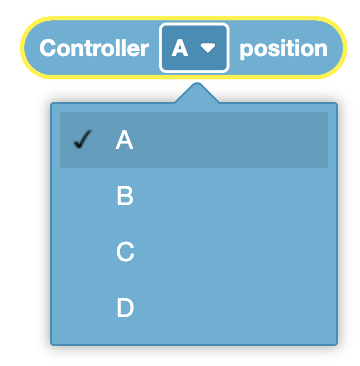
Position of Controller#
The Position of Controller block is used to report the position of a joystick on the IQ Controller along an axis.
(Controller [A v] position)
The Position of Controller block reports a range from -100 to 100.
The Position of Controller block reports 0 when the joystick axis is centered.
Choose the joystick’s axis.
In this example, the Brain will print the C axis of the IQ Controller’s joysticks.
  when started
  print (Controller [C v] position) on [Brain v] ◀ and set cursor to next row
Controller Enable/Disable#
The Controller Enable/Disable block is used to enable or disable Controller configured actions from the Devices menu.
Controller [Disable v]
Parameters |
Description |
|---|---|
state |
What state to set the controller to:
|
Example
    when started
    [Disable controller configured actions until drive is done.]
    Controller [Disable v]
    drive [forward v] for (6) [inches v] ▶
    Controller [Enable v]
Motor Sensing#
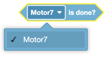
Motor is Done?#
The Motor is Done? block is used to report if the selected IQ Smart Motor or Motor Group has completed its movement.
<[Motor7 v] is done?>
The Motor is Done? block reports True when the selected Motor or Motor Group has completed its movement.
The Motor is Done? block reports False when the selected Motor or Motor Group is still moving.
Choose which Motor or Motor Group to use.
Motor is Spinning?#
The Motor is Spinning? block is used to report if the selected IQ Smart Motor or Motor Group is currently moving.
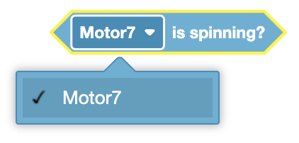
The Motor is Spinning? block reports True when the selected Motor or Motor Group is moving.
The Motor is Spinning? block reports False when the selected Motor or Motor Group is not moving.
Choose which Motor or Motor Group to use.
<[Motor7 v] is spinning?>
Position of Motor#
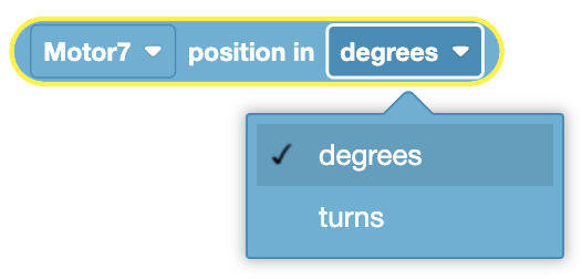
The Position of Motor block is used to report the distance an IQ Smart Motor or the first motor of a Motor Group has traveled.
([Motor7 v] position in [degrees v] :: custom-sensing)
Choose which Motor or Motor Group to use.
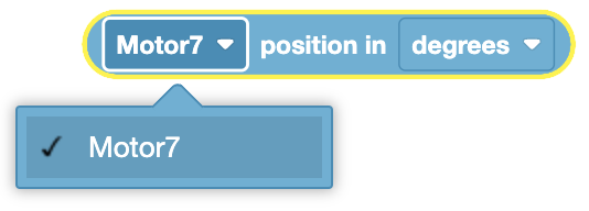
Choose the units to report in, degrees or turns.
In this example, the Motor will spin forward for 1 second before its current position is printed on the Brain’s screen.
  when started
  [Spin Motor7 forward for 1 second.]
  spin [Motor7 v] [forward v]
  wait (1) seconds
  [Print Motor7's current position in degrees.]
  print ([Motor7 v] position in [degrees v] :: custom-sensing) on [Brain v] ▶
Velocity of Motor#
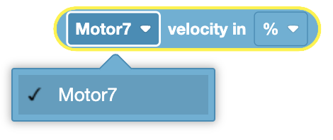
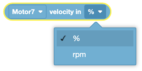
The Velocity of Motor block is used to report the current velocity of an IQ Smart Motor or the first motor of a Motor Group.
([Motor7 v] velocity in [% v])
The Velocity of Motor block reports a range from -100% to 100% or -600rpm to 600rpm.
Choose which Motor or Motor Group to use.
Choose the units to report in, percent (%) or rpm.
In this example, the Motor will spin forward for 1 second before its current velocity is printed on the Brain’s screen.
  when started
  [Spin Motor 7 forward for 1 second.]
  spin [Motor7 v] [forward v]
  wait (1) seconds
  [Print Motor7's current velocity in rpm.]
  print ([Motor7 v] velocity in [rpm v]) on [Brain v] ▶
Current of Motor#
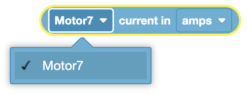
The Current of Motor block is used to report the amount of current a IQ Smart Motor or Motor Group is drawing in amperes (amps).
([Motor7 v] current in [amps v])
Choose which Motor or Motor Group to use.
In this example, the Motor will spin forward for 1 second before its current is printed on the Brain’s screen.
  when started
  [Spin Motor7 forward for 1 second.]
  spin [Motor7 v] [forward v]
  wait (1) seconds
  [Print Motor7's current velocity in amps.]
  print ([Motor7 v] current in [amps v]) on [Brain v] ▶
Drivetrain Sensing#
Drive is Done?#
The Drive is Done? block is used to report if the Drivetrain has completed its movement.
<drive is done?>
The Drive is Done? block reports True when the Drivetrain’s motors have completed their movement.
The Drive is Done? block reports False when the Drivetrain’s motors are still moving.
Drive is Moving?#
The Drive is Moving? block is used to report if the Drivetrain is currently moving.
<drive is moving?>
The Drive is Moving? block reports True when the Drivetrain’s motors are moving.
The Drive is Moving? block reports False when the Drivetrain’s motors are not moving.
Drive Heading#
The Drive Heading block is used to report the direction that the Drivetrain is facing by using the Inertial sensor’s current angular position.
(drive heading in degrees)
The Drive Heading block reports a range from 0.0 to 359.99 degrees.
In this example, the Drivetrain will turn to the right for 1 second before its current heading is printed on the Brain’s screen.
  when started
  [Turn towards the right for 1 second.]
  turn [right v]
  wait (1) seconds
  [Print Drivetrain's current heading after 1 second.]
  print (drive heading in degrees) on [Brain v] ◀ and set cursor to next row
Drive Rotation#
The Drive Rotation block is used to report the Drivetrain’s angle of rotation.
(drive rotation in degrees)
A clockwise direction is reported as a positive value, and a counterclockwise value is reported as a negative value.
In this example, the Drivetrain will turn to the left for 1 second before its current rotation is printed on the Brain’s screen.
  when started
  [Turn towards the right for 1 second.]
  turn [right v]
  wait (1) seconds
  [Print Drivetrain's current rotation after 1 second.]
  print (drive rotation in degrees) on [Brain v] ◀ and set cursor to next row
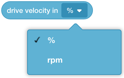
Drive Velocity#
The Drive Velocity block is used to report the current velocity of the Drivetrain.
(drive velocity in [% v])
The Drive Velocity block reports a range from -100% to 100% or -600rpm to 600rpm.
Choose the units to report in, percent (%) or rpm.
In this example, the Drivetrain will drive forward for 1 second before its current velocity is printed on the Brain’s screen.
  when started
  [Drive forward for 1 second.]
  drive [forward v]
  wait (1) seconds
  [Print Drivetrain's current velocity after 1 second.]
  print (drive velocity in [% v]) on [Brain v] ◀ and set cursor to next row
Drive Current#
The Drive Current block is used to report the amount of current (power) that the Drivetrain is currently using.
(drive current in [amps v])
In this example, the Drivetrain will drive forward for 1 second before its current is printed on the Brain’s screen.
  when started
  [Drive forward for 1 second.]
  drive [forward v]
  wait (1) seconds
  [Print Drivetrain's current after 1 second.]
  print (drive current in [amps v]) on [Brain v] ◀ and set cursor to next row
Bumper Sensing#
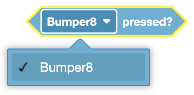
Bumper Pressed#
The Bumper Pressed block is used to report if the Bumper Switch is pressed.
<[Bumper8 v] pressed?>
The Bumper Pressed block reports True when the selected Bumper Switch is pressed.
The Bumper Pressed block reports False when the selected Bumper Switch is not pressed.
Choose which Bumper Switch to use.
In this example, the Brain will print a message on its screen the first time the Bumper Switch is pressed.
  when started
  [Don't print the message until the bumper is pressed.]
  wait until <[Bumper8 v] pressed?>
  print [Bumper was pressed.] on [Brain v] ▶
Touch LED Sensing#
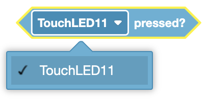
Touch LED Pressed#
The Touch LED Pressed block is used to report if the Limit Switch is pressed.
<[TouchLED11 v] pressed?>
The Touch LED Pressed block reports True when the selected Touch LED is pressed.
The Touch LED Pressed block reports False when the selected Touch LED is not pressed.
Choose which Limit Switch to use.
In this example, the Brain will print a message on its screen the first time the Touch LED is pressed.
  when started
  [Don't print the message until the Touch LED Sensor is pressed.]
  wait until <[TouchLED11 v] pressed?>
  print [Touch LED was pressed.] on [Brain v] ◀ and set cursor to next row
Gyro Sensing#
Calibrate Gyro#
The Calibrate Gyro block is used to calibrate the VEX IQ Gyro Sensor is used to reduce the amount drift generated by Gyro Sensor.
The Gyro Sensor must remain still during the calibration process.
calibrate [Gyro5 v] for [2 v] seconds
Choose which Gyro Sensor to use.
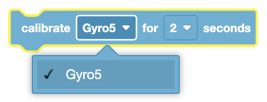
Choose how long to calibrate the Gyro Sensor for:
2 seconds
4 seconds
8 seconds
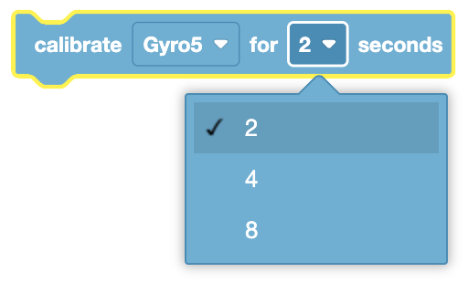
In this example, the Brain’s Gyro Sensor will calibrate for 2 seconds before printing the current heading of the Gyro Sensor.
  when started
  calibrate [Gyro5 v] for [2 v] seconds
  print ([Gyro5 v] heading in degrees) on [Brain v] ◀ and set cursor to next row
Set Heading#
The Set Heading block is used to set the Gyro Sensor current heading position to the specified value.
set [Gyro5 v] heading to (0) degrees
The Set Heading block accepts a range of 0.0 to 359.99 degrees.
Choose which Gyro Sensor to use.
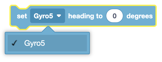
In this example, the Brain’s Gyro sensor will print its starting heading, set its heading to 90 degrees, and then print the new heading.
  when started
  print ([Gyro5 v] heading in degrees) on [Brain v] ◀ and set cursor to next row
  set [Gyro5 v] heading to (90) degrees
  print ([Gyro5 v] heading in degrees) on [Brain v] ◀ and set cursor to next row
Set Rotation#
The Set Rotation block is used to set the Gyro Sensor current rotation position to the specified value.
set [Gyro5 v] rotation to (0) degrees
The Set Rotation block accepts any positive or negative decimal or integer number.
Choose which Gyro Sensor to use.
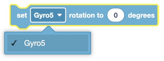
In this example, the Brain’s Gyro Sensor will print its starting rotation, set its rotation to -100 degrees, and then print the new rotation.
  when started
  print ([Gyro5 v] rotation in degrees) on [Brain v] ◀ and set cursor to next row
  set [Gyro5 v] rotation to (-100) degrees
  print ([Gyro5 v] rotation in degrees) on [Brain v] ◀ and set cursor to next row
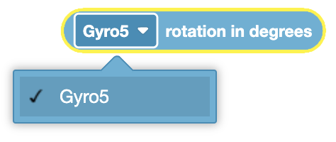
Angle of Heading#
The Angle of Heading block is used to report the VEX IQ Gyro Sensor’s current heading in degrees.
([Gyro5 v] heading in degrees)
The Angle of Heading block reports a range from 0.0 to 359.99 degrees.
Choose which Gyro Sensor to use.
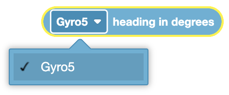
In this example, the Brain’s Gyro sensor will print its starting heading, set its heading to 90 degrees, and then print the new heading.
  when started
  print ([Gyro5 v] heading in degrees) on [Brain v] ◀ and set cursor to next row
  set [Gyro5 v] heading to (90) degrees
  print ([Gyro5 v] heading in degrees) on [Brain v] ◀ and set cursor to next row
Angle of Rotation#
The Angle of Rotation block is used to report the VEX IQ Gyro Sensor’s current rotation in degrees.
([Gyro5 v] rotation in degrees)
A clockwise direction is reported as a positive value, and a counterclockwise value is reported as a negative value.
Choose which Gyro Sensor to use.
In this example, the Brain’s Inertial sensor will print its starting rotation, set its rotation to -100 degrees, and then print the new heading.
  when started
  print ([Gyro5 v] rotation in degrees) on [Brain v] ◀ and set cursor to next row
  set [Gyro5 v] rotation to (-100) degrees
  print ([Gyro5 v] rotation in degrees) on [Brain v] ◀ and set cursor to next row
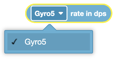
Rate of Gyro#
The Rate of Gyro block is used to report the VEX IQ Gyro Sensor’s rate of angular velocity.
([Gyro5 v] rate in dps)
The Rate of Gyro block reports a range between 0 to 249.99 dps.
Choose which Gyro Sensor to use.
In this example, the current Gyro Sensor’s rate will be printed to the Brain’s screen.
  when started
  print ([Gyro5 v] rate in dps) on [Brain v] ◀ and set cursor to next row
Color Sensing#
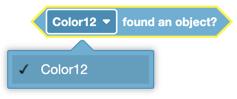
Color Sensor Found an Object#
The Color Sensor Found an Object block is used to report if the VEX IQ Color Sensor detects an object.
<[Color12 v] found an object?>
The Color Sensor Found an Object block reports True when the Color Sensor detects an object or surface close to the front of the sensor.
The Color Sensor Found an Object block reports False when the Color Sensor does not detect an object or surface close to the front of the sensor.
Choose which Color Sensor to use.
In this example, when the Color Sensor detects an object, it will print a message to the Brain.
  when started
  [Don't print the message until the Color Sensor detects an object.]
  wait until <[Color12 v] found an object?>
  print [Color Sensor detected an object.] on [Brain v] ◀ and set cursor to next row
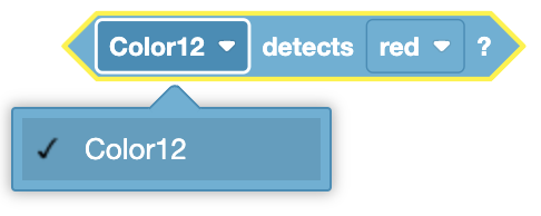
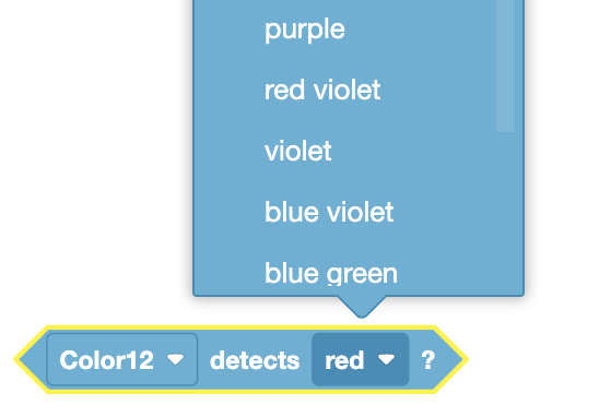
Color Sensor Detects Color#
The Color Sensor Detects Color block is used to report if the VEX IQ Color Sensor detects a specific color.
<[Color12 v] detects [red v]?>
The Color Sensor Detects Color block reports True when the Color Sensor detects the selected color.
The Color Sensor Detects Color block reports False when the Color Sensor detects a different color than the one selected.
Choose which Color Sensor to use.
Choose which color to detect.
In this example, when the Color Sensor detects the color green, it will print the detected color to the Brain.
  when started
  [Don't print the message until the Color Sensor detects an the color green.]
  wait until <[Color12 v] detects [green v]?>
  print ([Color12 v] color name) on [Brain v] ◀ and set cursor to next row
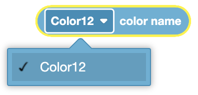
Color Sensor Color Name#
The Color Sensor Color Name block is used to report the name of the color detected by the VEX IQ Color Sensor.
([Color12 v] color name)
Choose which Color Sensor to use.
In this example, when the Color Sensor detects the color green, it will print the detected color to the Brain.
  when started
  [Don't print the message until the Color Sensor detects an the color green.]
  wait until <[Color12 v] detects [green v]?>
  print ([Color12 v] color name) on [Brain v] ◀ and set cursor to next row
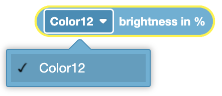
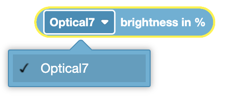
Color Sensor Brightness#
The Color Sensor Brightness block is used to report the amount of light detected by the VEX IQ Color Sensor.
([Color12 v] brightness in %)
Choose which Color Sensor to use.
In this example, the Color Sensor will print the current brightness to the Brain.
  when started
  print ([Color12 v] brightness in %) on [Brain v] ◀ and set cursor to next row
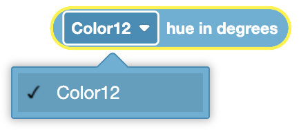
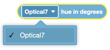
Color Sensor Hue#
The Color Sensor Hue block is used to report the hue of the color detected by the VEX IQ Color Sensor.
The Color Sensor Hue block reports a range from 0 to 360.
([Color12 v] hue in degrees)
Choose which Color Sensor to use.
In this example, the Color Sensor will print the current brightness to the Brain.
  when started
  print ([Color12 v] hue in degrees) on [Brain v] ◀ and set cursor to next row
Distance Sensing#
IQ (1st gen)#
To use the IQ (1st gen) Distance Sensing blocks, you must be using an IQ (1st gen) Distance Sensor.
Distance Sensor Found Object#
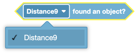
The Distance Sensor Found Object block is used to report if the Distance Sensor sees an object within its field of view.
<[Distance9 v] found an object?>
The Distance Sensor Found Object block reports True when the Distance Sensor sees an object or surface within its field of view.
The Distance Sensor Found Object block reports False when the Distance Sensor does not detect an object or surface.
Choose which Distance Sensor to use.
In this example, when the Distance Sensor detects an object, it will print the distance between it and the detected object.
  when started
  [Don't print the message until the Distance Sensor detects an object.]
  wait until <[Distance9 v] found an object?>
  print ([Distance9 v] distance in [mm v]) on [Brain v] ◀ and set cursor to next row
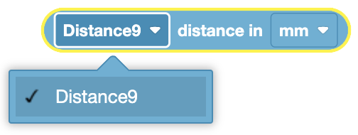
Object Distance#
The Object Distance block is used to report the distance of the nearest object from the Distance Sensor.
([Distance9 v] distance in [mm v])
The Object Distance block reports a range from 24mm to 1000mm or 1 inch to 40 inches.
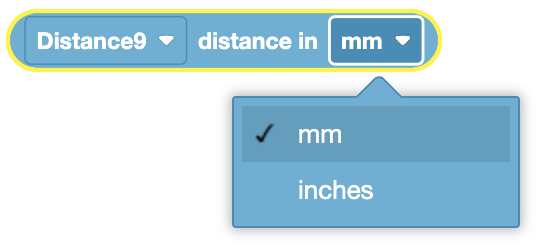
Choose which Distance Sensor to use.
Choose what units to report in: millimeters (mm) or inches.
In this example, when the Distance Sensor detects an object, it will print the distance between it and the detected object.
  when started
  [Don't print the message until the Distance Sensor detects an object.]
  wait until <[Distance9 v] found an object?>
  print ([Distance9 v] distance in [mm v]) on [Brain v] ◀ and set cursor to next row
IQ (2nd gen)#
To use the IQ (2nd gen) Distance Sensing blocks, you must be using an IQ (2nd gen) Distance Sensor.
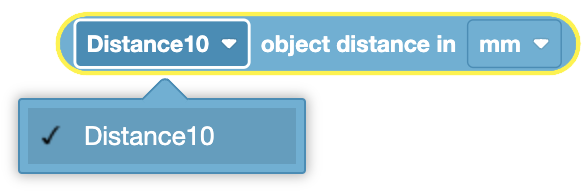
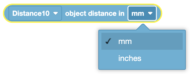
Object Distance#
The Object Distance block is used to report the distance of the nearest object from the Distance Sensor.
([Distance10 v] object distance in [mm v])
The Object Distance block reports a range from 20mm to 2000mm.
Choose which Distance Sensor to use.
Choose what units to report in: millimeters (mm) or inches.
In this example, when the Distance Sensor detects an object, it will print the distance between it and the detected object.
  when started
  [Don't print the message until the Distance Sensor detects an object.]
  wait until <[Distance10 v] found an object?>
  print ([Distance10 v] object distance in [mm v]) on [Brain v] ◀ and set cursor to next row
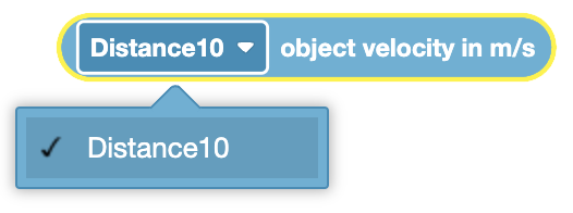
Object Velocity#
The Object Velocity block is used to report the current velocity of an object in meters per second (m/s).
([Distance10 v] object velocity in m/s)
Choose which Distance Sensor to use.
In this example, the Distance Sensor will report the current velocity of an object moving in front of it.
  when started
  print ([Distance10 v] object velocity in m/s) on [Brain v] ◀ and set cursor to next row
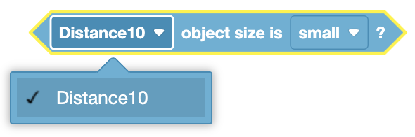
Object Size Is#
The Object Size Is block is used to report if the Distance Sensor detects the specified object size.
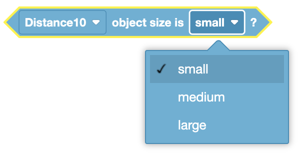
<[Distance10 v] object size is [small v]?>
The Distance Sensor determines the size of the object detected (none, small, medium, large) based on the amount of light reflected and returned to the sensor.
The Object Size Is block reports True when the Distance Sensor detects the specified size.
The Object Size Is block reports False when the Distance Sensor doesn’t detect the specified size.
Choose which Distance Sensor to use.
Choose which size of the object you want the Object Sensor to check for.
small
medium
large
In this example, if the Distance Sensor detects a small object, it will drive forward until the object is large.
  when started
  [Check if the Distance Sensor sees a small object.]
  if <[Distance10 v] object size is [small v]?> then
  [If a small object is detected, drive forward.]
  drive [forward v]
  [Wait until the small detected object is large.]
  wait until <[Distance10 v] object size is [large v]?>
  [When the object size is large, stop driving.]
  stop driving
  end
Distance Sensor Found Object#
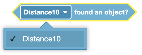
The Distance Sensor Found Object block is used to report if the Distance Sensor sees an object within its field of view.
<[Distance10 v] found an object?>
The Distance Sensor Found Object block reports True when the Distance Sensor sees an object or surface within its field of view.
The Distance Sensor Found Object block reports False when the Distance Sensor does not detect an object or surface.
Choose which Distance Sensor to use.
In this example, when the Distance Sensor detects an object, it will print the distance between it and the detected object.
  when started
  [Don't print the message until the Distance Sensor detects an object.]
  wait until <[Distance10 v] found an object?>
  print ([Distance10 v] object distance in [mm v]) on [Brain v] ◀ and set cursor to next row
Optical Sensing#
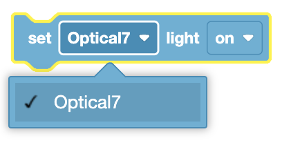
Set Optical Light#
The Set Optical Light block is used to set the light on the Optical Sensor to on or off. The light lets the Optical Sensor see objects if it is looking at an object in a dark area.
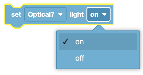
set [Optical7 v] light [on v]
Choose which Optical Sensor to use.
Choose whether to turn the light on or off.
In this example, the Optical Sensor will turn its light on for two seconds before turning it off.
  when started
  set [Optical7 v] light [on v]
  wait (2) seconds
  set [Optical7 v] light [off v]
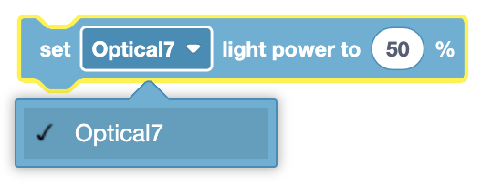
Set Optical Light Power#
The Set Optical Light Power block is used to set the light power of Optical sensor
set [Optical7 v] light power to (50)%
The Set Optical Light Power block block accepts a range of 0% to 100%. This will change the brightness of the light on the Optical Sensor. If the light is off, this block will turn the light on.
Choose which Optical Sensor to use.
In this example, the Optical Sensor’s power light is set to 75% before it waits to detect an object to print a message.
  when started
  set eye light power to (75)%
  [Wait until the Eye Sensor detects an object.]
  wait until <eye found an object?>
  print [Object detected.] ◀ and set cursor to next row
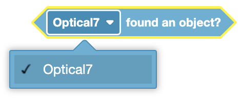
Optical Sensor Found Object#
The Optical Sensor Found Object block is used to report if the Optical Sensor detects an object close to it.
<eye found an object?>
The Optical Sensor Found Object block reports True when the Optical Sensor detects an object close to it.
The Optical Sensor Found Object block reports False when an object is not within range of the Optical Sensor.
Choose which Optical Sensor to use.
In this example, the Optical Sensor’s power light is set to 75% before it waits to detect an object to print a message.
  when started
  set eye light power to (75)%
  [Wait until the Eye Sensor detects an object.]
  wait until <eye found an object?>
  print [Object detected.] ◀ and set cursor to next row
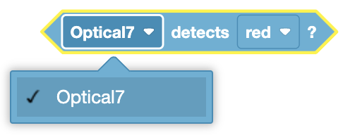
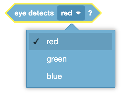
Optical Sensor Detects Color#
The Optical Sensor Detects Color block is used to report if the Optical Sensor detects the specified color.
<eye detects [red v]?>
The Optical Sensor Detects Color block reports True when the Optical Sensor detects the specified color.
The Optical Sensor Detects Color block reports False when the Optical Sensor doesn’t detect the specified color.
Choose which Optical Sensor to use.
Choose which color the Optical Sensor will check for.
In this example, the Optical Sensor will wait until it detects a red color before printing the color on the Brain’s screen.
  when started
  [Wait until the Eye Sensor detects the color red.]
  wait until <eye detects [red v]?>
  print [Color red detected.] ◀ and set cursor to next row
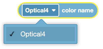
Optical Sensor Color Name#
The Optical Sensor Color Name block is used to report the name of the color detected by the VEX IQ Optical Sensor.
([Optical4 v] color name)
The Color Name block reports one the following colors:
red
green
blue
yellow
orange
purple
cyan
Choose which Optical Sensor to use.
In this example, the Optical Sensor will wait until it detects a red color before printing the color on the Brain’s screen.
  when started
  [Wait until the Eye Sensor detects the color red.]
  wait until <eye detects [red v]?>
  print [Color red detected.] ◀ and set cursor to next row
Optical Brightness#
The Optical Brightness block is used to report the amount of light detected by the Optical Sensor.
(eye brightness in %)
The Optical Brightness block reports a number value from 0% to 100%.
A large amount of light detected will report a high brightness value.
A small amount of light detected will report a low brightness value.
Choose which Optical Sensor to use.
In this example, the Optical Sensor will print the current brightness value to the Brain’s screen.
  when started
  print (eye brightness in %) ◀ and set cursor to next row
Optical Hue#
The Optical Hue block is used to report the hue of the color of an object.
(eye hue in degrees)
The Optical Hue block reports a number value that is the hue of the color of an object. It returns a number between 0 and 359.
The value can be thought of as the location of the color on a color wheel in degrees.
Choose which Optical Sensor to use.
In this example, the Optical Sensor will print the currently seen hue to the Brain’s screen.
  when started
  print (eye hue in degrees) ◀ and set cursor to next row
Vision Sensing#
take Vision Sensor snapshot#
The take Vision Sensor snapshot block filters data from the Vision Sensor frame. The Vision Sensor can detect signatures that include configured colors and color codes.
Colors and color codes must be configured first in the Vision Utility before they can be used with this block.
The dataset stores objects ordered from largest to smallest by width, starting at item 1. Each object’s properties can be accessed using Vision object property block. An empty dataset is returned if no matching objects are detected.
take a [Vision1 v] snapshot of [SELECT_A_SIG v]
Parameter |
Description |
|---|---|
vision |
The Vision Sensor to use, configured in the Devices window. |
signature |
The color signature or color code to analyze in the snapshot. |
Example
  when started
  [Move forward if a red box is detected.]
  forever
  take a [Vision1 v] snapshot of [RED_BOX v]
  if <[Vision1 v] object exists?> then
  drive [forward v] for [10] [mm v] ▶
set Vision Sensor object item#
The set Vision Sensor object item block sets which item in the dataset to use.
set [Vision1 v] object item to (1)
Parameter |
Description |
|---|---|
vision |
The Vision Sensor to use, configured in the Devices window. |
item |
The number of the item in the dataset to use. |
Example
  when started
  [Display the largest detected red object.]
  forever
  take a [Vision1 v] snapshot of [RED_BOX v]
  clear all rows on [Brain v]
  set cursor to row [1] column [1] on [Brain v]
  if <[Vision1 v] object exists?> then
  set [Vision1 v] object item to (1)
  print ([Vision1 v] object [width v]) on [Brain v] ▶
  end
  wait [0.5] seconds
Vision Sensor object count#
The Vision Sensor object count block returns the number of detected objects in the dataset as an integer.
([Vision1 v] object count)
Parameter |
Description |
|---|---|
vision |
The Vision Sensor to use, configured in the Devices window. |
Example
  when started
  [Display the amount of red objects.]
  forever
  clear all rows on [Brain v]
  set cursor to row [1] column [1] on [Brain v]
  take a [Vision1 v] snapshot of [RED_BOX v]
  if <[Vision1 v] object exists?> then
  print ([Vision1 v] object count) on [Brain v] ▶
  end
  wait [0.5] seconds
Vision Sensor object exists?#
The Vision Sensor object exists? block returns a Boolean indicating whether any object is detected in the dataset.
True – The dataset includes a detected object.
False – The dataset does not include any detected objects.
<[Vision1 v] object exists?>
Parameter |
Description |
|---|---|
vision |
The Vision Sensor to use, configured in the Devices window. |
Example
  when started
  [Move forward if a red box is detected.]
  forever
  take a [Vision1 v] snapshot of [RED_BOX v]
  if <[Vision1 v] object exists?> then
  drive [forward v] for [10] [mm v] ▶
Vision Sensor object property#
There are five properties that are included with each object (shown below) stored after the take Vision Sensor snapshot block is used.
([Vision1 v] object [width v])
Some property values are based off of the detected object’s position in the Vision Sensor’s view at the time that the take Vision Sensor snapshot block was used. The Vision Sensor has a resolution of 316 by 212 pixels.
Parameter |
Description |
|---|---|
vision |
The Vision Sensor to use, configured in the Devices window. |
property |
Which property of the detected object to use: |
width#
width returns the width of the detected object in pixels as an integer from 0 to 316.
([Vision1 v] object [width v])
Example
  when started
  [Move towards a red object until its width is larger than 100 pixels.]
  forever
  take a [Vision1 v] snapshot of [RED_BOX v]
  if <[Vision1 v] object exists?> then
  if <([Vision1 v] object [width v]) [math_less_than v] [100]> then
  drive [forward v]
  end
  else
  stop driving
height#
height returns the height of the detected object in pixels as an integer from 0 to 212.
([Vision1 v] object [height v])
Example
  when started
  [Move towards a red object until its height is larger than 100 pixels.]
  forever
  take a [Vision1 v] snapshot of [RED_BOX v]
  if <[Vision1 v] object exists?> then
  if <([Vision1 v] object [height v]) [math_less_than v] [100]> then
  drive [forward v]
  end
  else
  stop driving
centerX#
centerX returns the x-coordinate of the center of the detected object in pixels as an integer from 0 to 316.
([Vision1 v] object [centerX v])
Example
  when started
  [Turn slowly until a red object is centered in front of the Vision Sensor.]
  set turn velocity to [30] [% v]
  turn [right v]
  forever
  take a [Vision1 v] snapshot of [RED_BOX v]
  if <[Vision1 v] object exists?> then
  if <<[140] [math_less_than v] ([Vision1 v] object [centerX v])> and <([Vision1 v] object [centerX v]) [math_less_than v] [180]>> then
  stop driving
centerY#
centerY returns the y-coordinate of the center of the detected object in pixels as an integer from 0 to 212.
([Vision1 v] object [centerY v])
Example
  when started
  [Move towards a red object until its center y-coordinate is more than 140 pixels.]
  forever
  take a [Vision1 v] snapshot of [RED_BOX v]
  if <[Vision1 v] object exists?> then
  if <([Vision1 v] object [centerY v]) [math_less_than v] [140]> then
  drive [forward v]
  end
  else
  stop driving
angle#
angle returns the orientation of the detected Color Code as an integer in degrees from 0 to 180.
([Vision1 v] object [angle v])
Example
  when started
  [Turn left or right depending on how the Color Code is rotated.]
  forever
  take a [Vision1 v] snapshot of [BOX_CODE v]
  if <[Vision1 v] object exists?> then
  if <<[70] [math_less_than v] ([Vision1 v] object [angle v])> and <([Vision1 v] object [angle v]) [math_less_than v] [110]>> then
  turn [right v] for (45) degrees ▶
  else if <<[250] [math_less_than v] ([Vision1 v] object [angle v])> and <([Vision1 v] object [angle v]) [math_less_than v] [290]>> then
  turn [left v] for (45) degrees ▶
  else
  stop driving
  end