GPS Sensing#
To make GPS Sensor blocks appear in VEXcode V5, a GPS (Game Positioning System™) Sensor must be configured in the Devices window.
For more information, refer to these articles:
GPS Calibrate#
The GPS Calibrate block calibrates the GPS Sensor when the sensor has been configured as a part of a V5 Drivetrain. This will set the GPS’ configured heading (according to its angle offset) as the current heading of the Drivetrain.
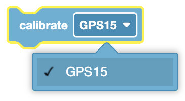
calibrate [GPS15 v]
Choose which GPS Sensor to use.
In this example, the GPS Sensor will calibrate, then the heading of the sensor is used to turn the robot to the 180 degree heading of the Field.
  when started
  [Turn to face the lower Field wall using data from the GPS Sensor.]
  calibrate [DrivetrainGPS v]
  turn to heading (180) degrees ▶
Set GPS Location#
The Set GPS Location block is used to set the X, Y coordinates, and heading of a GPS Sensor to a known value at the beginning of a project. This can be done to help reduce GPS data inaccuracies due to the sensor’s proximity to field walls when a project is started.
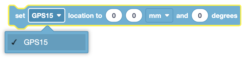
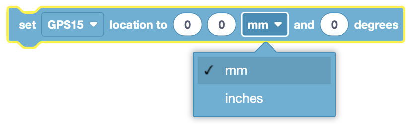
set [GPS15 v] location to (0) (0) [mm v] and (0) degrees
When a GPS Sensor is too close to the field walls to read the Field Code (for example, when a robot is in a game’s starting position on a field), unexpected behaviors can often occur if the code relies on the GPS’s coordinate and heading data.
Choose which GPS Sensor to use.
Input the X and Y coordinates of the reference point on your robot on the field in this known location. The reference point on your robot is the same location that was used to calculate the offsets when configuring the GPS Sensor.
Choose the units to use for the X and Y coordinates.
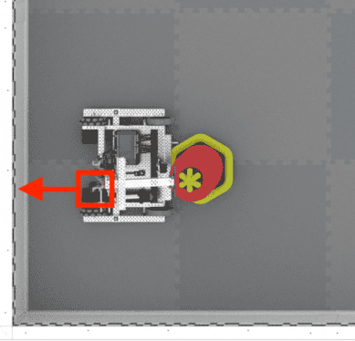
The last input is the heading of the reference point on your robot. Using the example image above, the GPS Sensor is mounted facing behind the robot, while the reference point is at the end of the arm on the robot. Because the reference point is facing the right wall (heading of 90), the heading value that should be input is 90.
The example shown here sets the X and Y location of the robot to the starting position at the beginning of the project.
  when started
  [Wait so the GPS has time to initialize.]
  wait (0.5) seconds
  [Set the starting to the bottom left corner of the Field facing the right wall.]
  set [GPS20 v] location to (-1200) (-1200) [mm v] and (90) degrees
GPS Position#
The GPS Position block is used to report the X or Y coordinate location of a GPS Sensor on the Field.
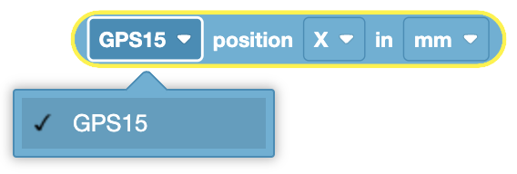
([GPS15 v] position [X v] in [mm v])
By default the GPS position reporter block reports either the X or Y coordinate location of a GPS Sensor.
If an offset is added when configuring the GPS Sensor, then the reported X or Y position will be of the reference point on the robot.
Choose a GPS Sensor to report the position of.
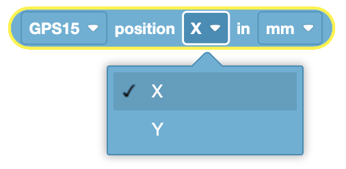
Choose what axis to report the position of: X or Y.
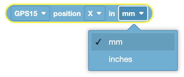
Choose what units the position will be reported in: millimeters (mm) or inches.
In this example, the robot (starting on the righthand side of the Field), drives towards the center until the X position is reported as less than 0mm. Then the robot stops driving.
  when started
  [Drive slowly towards the center of the Field.]
  set drive velocity to (20) [% v]
  drive [forward v]
  [Stop driving when the GPS reports an X position near the center of the Field.]
  wait until <([GPS20 v] position [X v] in [mm v] ) [math_less_than v] (0)>
  stop driving
GPS Heading#
The GPS Heading block is used to report the heading of a GPS Sensor on a Field based on the sensor’s readings from the GPS Field Code.
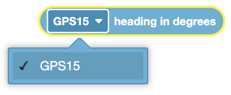
([GPS15 v] heading in degrees)
The GPS heading reporter block reports a range from 0.00 to 359.99 degrees.
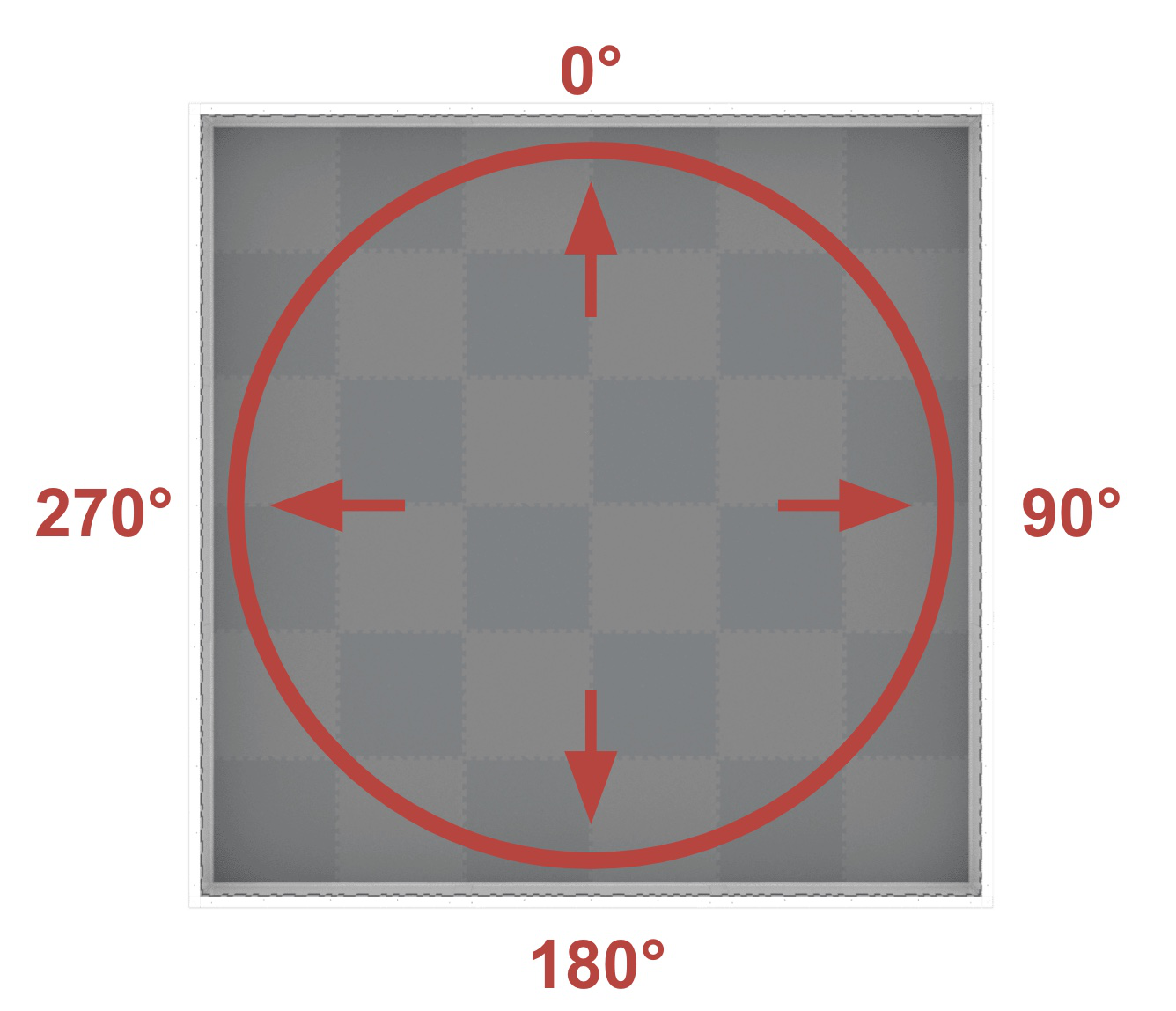
The heading corresponds to the Field heading, which is a range of 0º to 359.9º in the clockwise direction. The 0º is in the 12 o’clock position.
By default the GPS heading reporter block reports the heading of a GPS Sensor.
If an Angle Offset is added when configuring the GPS Sensor, then the reported heading will be of the reference point on the robot.
Choose a GPS Sensor to report the heading of.
In this example, the robot (starting facing the 12 o-clock position of the Field), turns towards the right wall of the Field until the heading is reported as greater than 90 degrees. Then the robot stops driving.
  when started
  [Turn slowly to face the right wall.]
  set turn velocity to (20) [% v]
  turn [right v]
  [Stop turning when the GPS reports a heading greater than 90 degrees..]
  wait until <([GPS20 v] heading in degrees ) [math_greater_than v] (90)>
  stop driving
GPS Acceleration#
The GPS Acceleration block is used to report the acceleration value of the specified axis on a GPS Sensor.
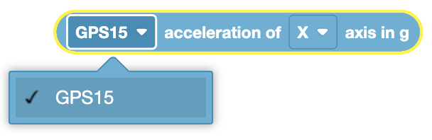
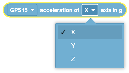
([GPS15 v] acceleration of [X v] axis in g)
The GPS Acceleration block reports a range of values from -4.0 to 4.0 Gs.
Choose which GPS Sensor to use.
Choose which axis to report the acceleration of:
X - reports acceleration of the GPS Sensor’s forward and backward rotations.
Y - reports acceleration of the GPS Sensor’s left and right rotations.
Z - reports acceleration of the GPS Sensor’s up and down movements.
In this example, the robot will move forward, and after 1 second report its current acceleration on the X and Y axes.
  when started
  [Drive forward for one second.]
  drive [forward v]
  wait (1) seconds
  [Print the X and Y accelerations as the Drivetrain moves.]
  print ([GPS15 v] acceleration of [X v] axis in g) on [Brain v] ◀ and set cursor to next row
  print ([GPS15 v] acceleration of [Y v] axis in g) on [Brain v] ◀ and set cursor to next row
GPS Gyro Rate#
The GPS Gyro Rate block is used to report the the rate of rotation from the specified axis on a GPS Sensor.
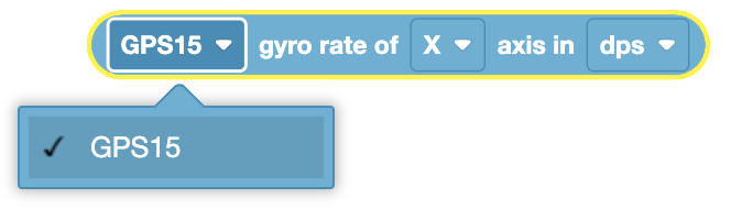
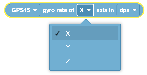
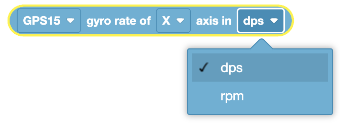
([GPS15 v] gyro rate of [X v] axis in [dps v])
The GPS Gyro Rate block reports a range from -1000 to 1000 degrees per second (dps), or -167 to 167 revolutions per minute (rpm).
Choose which GPS Sensor to use.
Choose which axis to report the acceleration of:
X - reports rate of rotation when a GPS Sensor rotates in the X-Axis.
Y - reports rate of rotation when a GPS Sensor rotates in the Y-Axis.
Z - reports rate of rotation when a GPS Sensor rotates in the Z-Axis.
Choose what unit to report the gyro rate in: dps or rpm.
In this example, the robot will turn towards the left, and after 1 second report its current gyro rate of the X axis.
  when started
  [Turn towards the left for one second.]
  turn [left v]
  wait (1) seconds
  [Print the gyro rate of the X axis as the Drivetrain turns.]
  print ([GPS15 v] gyro rate of [X v] axis in [dps v]) on [Brain v] ◀ and set cursor to next row
GPS Orientation#
The GPS Orientation block is used to report the orientation of the specified axis on a GPS Sensor.
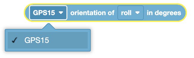
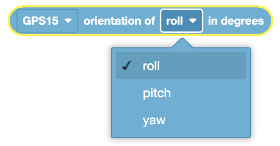
([GPS15 v] orientation of [roll v] in degrees)
Choose which GPS Sensor to use.
Choose which axis to report the orientation of:
roll - reports a value between -180 to +180 degrees, representing the angle of a GPS Sensor when tilted left or right.
pitch - reports a value between -90 to +90 degrees, representing the angle of a GPS Sensor when tilted forward or backwards.
yaw - reports a value between -180 to +180 degrees, representing the angle of a GPS Sensor when rotated about the vertical axis.
In this example, the robot will turn towards the left, and after 1 second report its yaw.
  when started
  [Turn towards the left for one second.]
  turn [left v]
  wait (1) seconds
  [Print the yaw as the Drivetrain turns.]
  print ([GPS15 v] orientation of [yaw v] in degrees) on [Brain v] ◀ and set cursor to next row
GPS Signal Quality#
The GPS Signal Quality block is used to report a numerical percentage value from 0-100 representing the current signal quality of a GPS Sensor.
Reported Value |
Description |
|---|---|
100 |
All reported positional and heading data from a GPS Sensor is valid. |
~90 |
Any positional data is no longer being calculated by capturing information from the VEX Field Code, but rather through alternative means. |
0 - 80 |
Only GPS Sensor heading values are valid, but as more time goes by where a GPS Sensor is not scanning enough of the VEX Field Code to accurately determine position and heading information, the reported signal quality will continue to drop until 0, where any GPS Sensor data is effectively frozen and no longer valid. |
([GPS15 v] signal quality in %)
Choose which GPS Sensor to use.
In this code snippet, the signal quality will constantly be checked due to the Forever loop. The TRUE branch will only run if the signal quality from the GPS Sensor is reporting values above 90, to ensure the GPS Sensor data being used in the project is valid.
  forever
  if <([GPS20 v] signal quality in %) [math_greater_than v] (90)> then
  else
  end